- Whatsapp: 8613738300923
- Email: [email protected]


Author: Gencel Stainless Steel Engineering Team — 3A and ISO 9001 certified stainless steel valve and pipe fitting manufacturer supplying food, beverage, dairy, pharmaceutical and biotech hygienic process lines.
Choosing between a manual and a pneumatic sanitary diaphragm valve is not a preference question — it is an operating model question. The valve body, the wetted materials and the hygiene performance are identical in both cases. What changes is who or what turns the handwheel, how the valve behaves when air is lost, and what the line costs to run for the next ten years.
This guide is written for procurement managers, project engineers and OEM buyers specifying hygienic valves for food, beverage, dairy, pharmaceutical, biotechnology and high-purity chemical service. It compares the two actuation options on the specification points that actually decide a tender — duty cycle, control air, fail position, cleaning validation, maintenance and total cost of ownership — using the published data for GENCEL diaphragm valve bodies, and closes with a checklist you can paste straight into an RFQ.
Two things are worth stating before the comparison. First, a sanitary diaphragm valve is a hygienic valve first and an actuated device second: whichever way you operate it, the diaphragm is what isolates the product from the stem, the bonnet and the outside world. Second, the manual vs pneumatic question is usually a per-point decision, not a project-wide one — most valve schedules end up with a mix, and the skill is knowing which points belong in which column.
Specify a manual diaphragm valve when the valve is operated by a person standing next to it: sampling points, drain points, bypass lines, manual transfer panels, pilot plants and skids that run a fixed recipe with no automation. Capital cost is lowest, no compressed air is required, and there is no actuator to validate.
Specify a pneumatic diaphragm valve when the valve must open and close as part of a CIP or SIP recipe, when it is mounted where an operator cannot safely reach it, when it cycles more than a few times per shift, or when the process demands a defined fail-open or fail-closed position on loss of air. The actuator adds cost but removes operator variability, and it is the only practical route to repeatable automated sequences.
Most plants need both. A typical hygienic line specifies manual valves at sample, drain and utility take-off points and pneumatic valves at every step the recipe controls. Standardising on one body design across both keeps the spare parts list down to a single diaphragm and a single actuator interface.
If you have not yet settled on the valve type itself — diaphragm versus butterfly, seat geometry versus full bore — read our sanitary diaphragm vs butterfly valve comparison first, then come back to the actuation decision.
Both configurations use exactly the same three functional parts. Understanding them makes the actuation decision much easier, because it shows that actuation changes almost nothing about hygiene.
● Valve body with a weir or straight-through bore — the weir type raises a ridge across the flow path so the diaphragm only has to travel a short distance to seal. That short stroke extends diaphragm life and makes the weir body the default for pharmaceutical and food service. The straight-through type offers a full bore for viscous products, slurries and piggable lines, at the cost of longer diaphragm travel and a shorter cycle life.
● Flexible diaphragm — the only moving part in contact with the product. It seals down onto the weir to close the line and flexes upward to open it.
● Compressor and stem — the compressor pushes the diaphragm onto the weir. The stem sits above the diaphragm and never touches the medium, which is why this valve needs no gland packing and no stem seal in the product zone.
That isolation is the whole reason a sanitary diaphragm valve is specified on aseptic service: the process medium only ever touches the valve body and the diaphragm, so there is no crevice, no packing and no dead leg where residue can survive a cleaning cycle. GENCEL builds this body as a sanitary diaphragm valve in SS304 or SS316L stainless steel with clamp, weld, thread or flange ends, in sizes from 1 inch to 4 inches (DN25 – DN100), to 3A, DIN, SMS, IDF and ISO end standards.
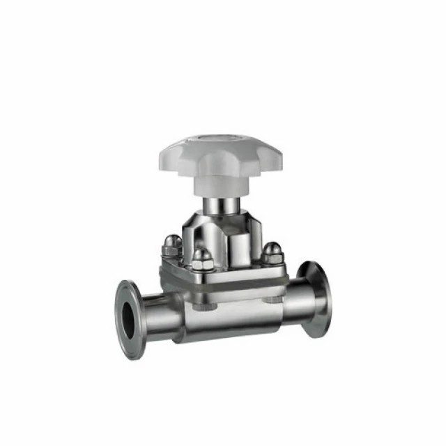
Replacing the handwheel with a pneumatic actuator does three things to the valve, and only one of them is obvious at the quoting stage.
● Closing force becomes constant. A handwheel is tightened by a person, and over-tightening is the single most common cause of premature diaphragm failure. An actuator is set to a defined air pressure and delivers the same closing force on every cycle, which is one reason automated diaphragms often outlast hand-operated ones on high-cycle lines.
● The valve gains a defined safe state. A spring-return actuator fails open or fails closed when air is lost; a double-acting actuator holds its last position. Specify which one you need — that is a process safety decision, not a hardware preference.
● The valve acquires a utility. GENCEL diaphragm valves are specified with a control air pressure of 5 – 8 bar. That air must be clean, dry and oil-free, because actuator seals and solenoid valves are far less tolerant of poor air quality than a handwheel is of a wet floor.
Everything else — bore, weir geometry, diaphragm material, surface finish, end connection and standards package — stays the same. This is why the actuation decision can be taken late in a project without re-validating a single wetted part.
The table below summarises the comparison points that most often decide a tender. Note rows 10 and 12: they are the reason you can specify both types from one supplier without running two qualification packages.
| Specification point | Manual (handwheel) | Pneumatic (air actuator) |
| Actuation source | Operator turns the handwheel | Compressed air, 5 – 8 bar control pressure |
| Typical duty | Intermittent, a few cycles per shift | Repetitive cycling under recipe control |
| Closing force | Operator dependent, risk of over-tightening | Repeatable, set by air pressure |
| Fail position | Stays where it was left | Spring return fail-open / fail-closed, or double-acting hold |
| Position feedback | Visual only | Optional feedback unit and switch box |
| Utilities required | None | Clean, dry, oil-free instrument air |
| Installed cost | Lowest | Higher — actuator, solenoid, air piping |
| Maintenance scope | Diaphragm and handwheel | Diaphragm, actuator seals, air preparation |
| Out-of-reach locations | Not suitable | Designed for it |
| Hygiene and cleanability | Identical body, identical CIP/SIP performance | Identical body, identical CIP/SIP performance |
| Best fit | Sample, drain, bypass and manual panels | CIP/SIP circuits, automated transfer, batching |
| Spare parts | One diaphragm across the plant | One diaphragm across the plant |
A pneumatic actuator adds to the capital cost of each valve, and then adds solenoid valves, air tubing and — on larger projects — an air preparation station. On a line with forty valves that difference is real money. It is also the wrong place to stop the calculation.
● Labour. Every manual valve in a cleaning sequence is a valve an operator has to walk to. On a plant running three CIP cycles a day, that walking is a recurring cost that never appears on a purchase order.
● Consistency. An automated sequence closes valves in the same order at the same point in the recipe every time. Manual operation introduces variation, and variation is what surfaces later as a failed swab test or a rejected batch.
● Diaphragm life. As noted above, over-tightened handwheels shorten diaphragm life. Actuators set to the correct air pressure remove that failure mode entirely.
● Inventory. Standardising one body across manual and pneumatic duty means one diaphragm part number, one compressor design and one seat geometry to hold in stock.
The practical rule: automate the valves the recipe controls and the valves that are hard to reach, and leave everything else manual. Over-automating a line is as common a budgeting mistake as under-automating it — a sanitary diaphragm valve with an actuator fitted to a drain point nobody sequences is simply money spent on compressed air.
Not sure which actuation your line needs?
Send us your valve schedule — line size, medium, temperature, cycle count and control philosophy — and our engineering team will mark up which points should be manual and which should be pneumatic, then price the whole sanitary diaphragm valve schedule in one bill of materials.
Actuation does not change the hygienic performance of the valve body, but it does change what you have to document and what you have to check at commissioning.
● The wetted surface stays identical. Both versions use the same SS304 or SS316L body, the same diaphragm and the same internal surface finish in the Ra 0.8 µm to 0.5 µm range, measured as an average roughness value according to ASME BPE surface classifications. Cleaning and sterilisation behaviour is unchanged.
● Drainability is an installation issue, not an actuation issue. GENCEL diaphragm bodies are shaped so cleaning liquid runs out completely rather than pooling in the cavity, but that only works if the valve is installed at the correct drain angle. Put the drain angle in the specification and verify it during commissioning.
● Add the actuator to the validation scope. If you automate, the actuator, its air supply and any position feedback become part of the qualified system. Ask for actuator material documentation, air quality requirements and the elastomer specification for the actuator seals.
● Request a pressure–temperature curve, not a single number. Pressure capability falls as temperature and diameter rise. Ask for the P–T curve for the exact sanitary diaphragm valve size and diaphragm material you are buying instead of relying on a headline rating measured at ambient conditions.
Choose the handwheel version wherever the valve is a point of deliberate human intervention:
● Sampling points and drain points on tanks, vessels and process lines.
● Bypass and manual transfer lines used during maintenance, changeover or cleaning.
● Pilot plants, laboratory skids and R&D lines where recipes change weekly.
● Utility take-offs — process water, condensate return, drain headers.
● Any location where an operator is already present and the valve is cycled a handful of times per day.
GENCEL builds the handwheel configuration as a dedicated manual diaphragm valve covering 1 inch to 4 inches (DN25 – DN100) in 304 or 316L, with EPDM or PTFE diaphragms and clamp, weld, thread or flange ends, to 3A, DIN, SMS, IDF and ISO standards. Because the handwheel sits above the diaphragm, the stem never enters the product zone, and the diaphragm remains the only routine wear item.
For a component-level breakdown of the handwheel design, see our article on the manual diaphragm valve definition, working principle and uses.
A pneumatic sanitary diaphragm valve is the right choice wherever the valve is part of a controlled, repeatable sequence rather than a manual intervention point:
● CIP and SIP circuits where valves must open and close in a fixed order with no operator input.
● Automated product transfer, routing and batching between vessels.
● Valves mounted above pipe racks, inside containment, or in any position an operator cannot reach safely.
● Lines that must fall to a defined safe position on loss of air.
● High-cycle duty where a consistent closing force will extend diaphragm service life.
Two specification points are easy to miss when you order the diaphragm valve actuator. First, state the fail position explicitly — fail-open, fail-closed or double-acting hold — because the actuator is built differently for each and it cannot be changed on site. Second, state the air quality you will supply: the 5 – 8 bar control air range assumes clean, dry, filtered air, and contamination in that line is the most common cause of actuator trouble after commissioning.
Where the duty is high-cycle utility service rather than aseptic product — CIP return, steam, water — an angle seat body is often the more economical choice; GENCEL’s pneumatic angle seat valve covers 0 – 2.5 MPa at −20 °C to +180 °C as standard, with a high-temperature version to +300 °C.
Use the worksheet below as a printable pre-purchase check for every sanitary diaphragm valve point on the line. Fill in your own requirement, compare it against the GENCEL reference value, and tick the last column once your supplier has confirmed each point in writing. Everything here can be answered by a manufacturer holding 304 and 316L stock.
| Checkpoint | Your requirement | GENCEL reference value | Confirmed |
| Nominal size | 1″ – 4″ (DN25 – DN100) | ☐ | |
| Body material | SS304 / SS316L | ☐ | |
| Diaphragm material | EPDM + PTFE (FPM on request) | ☐ | |
| Working pressure | 0 – 10 bar | ☐ | |
| Control air pressure | 5 – 8 bar, clean and dry | ☐ | |
| Medium temperature | EPDM −40 to +120 °C; PTFE and FPM −40 to +180 °C | ☐ | |
| End connection | Clamp / weld / thread / flange | ☐ | |
| Standard | 3A, DIN, SMS, IDF, ISO | ☐ | |
| Internal surface finish | Ra 0.8 – 0.5 µm | ☐ | |
| Actuation | Manual, pneumatic or electric | ☐ | |
| Fail position (pneumatic) | Spring return fail-open / fail-closed, or double-acting | ☐ | |
| Position feedback | Optional feedback and switch box | ☐ | |
| Certification | 3A, ISO 9001 | ☐ | |
| P–T curve for the exact size | Supplied on request with the quotation | ☐ |
Want this checklist filled in for you?
Email the worksheet with your line data and we will return it completed against our 304/316L sanitary diaphragm valve range, including the pressure–temperature curve, diaphragm recommendation and a firm quotation.
The diaphragm is the only routine wear part on the valve, and it sets the temperature ceiling for the whole assembly. Select it against your highest sterilising temperature, not against your normal process temperature.
● EPDM — −40 °C to +120 °C. The default choice for water, dairy, beverage and most food service, and the most cost-effective option wherever the temperature allows it.
● PTFE — −40 °C to +180 °C. Specified for high-temperature SIP, aggressive cleaning chemicals and pharmaceutical water systems.
● FPM — −40 °C to +180 °C. Used where the medium attacks EPDM but a full PTFE diaphragm is not justified.
For chemically aggressive service — strong acids, solvents, high-purity chemicals — specify an SS316L sanitary diaphragm valve body with a PTFE diaphragm, or step up to the fluorine-lined version: GENCEL also supplies a PFA, FEP or ETFE lined diaphragm valve body rated from −30 °C to +200 °C at 10 bar (145 PSI), with conductive anti-static lining options and FDA and USP compliance for food, pharmaceutical and biotech service. On every one of these, confirm the pressure–temperature curve for your exact size before sign-off: the figure on the datasheet is not the rating at 180 °C on a DN100 body.
Whichever actuation you specify, ask for the same document set. It is the fastest way to separate a manufacturer from a trading company, and it is the package your QA team will ask for during qualification.
● Material certificates for all wetted stainless steel parts, traceable to the melt.
● Certificates covering the 3A sanitary diaphragm valve body and the diaphragm elastomer, with FDA or USP compliance statements.
● Surface finish measurement report giving the measured Ra value of the valve body.
● Pressure–temperature curve for the exact size and diaphragm combination.
● Actuator data sheet with air quality requirement, control pressure range and fail position.
● Dimensional drawing showing the installed drain angle and overall height with actuator.
● Spare diaphragm part number and the recommended change interval for your duty cycle.
A manufacturer holding 304 and 316L stock and its own diaphragm inventory can normally answer all seven in one pass. A trading company will have to ask somebody, and the answer will arrive after your order deadline.
The manual version is opened by a handwheel; the pneumatic version uses 5 – 8 bar compressed air. Both share the same hygienic body, diaphragm and cleanability — only actuation and utilities differ.
Yes. The body, diaphragm and end connections are identical, so most GENCEL valves can take a pneumatic or electric actuator later without changing a wetted part or re-qualifying the line.
Yes. GENCEL pneumatic actuators are specified with a control air pressure of 5 – 8 bar, supplied clean, dry and oil-free to protect actuator seals and solenoid valves from contamination.
Pneumatic, on high-cycle lines. A constant pressure-set closing force avoids the over-tightening that shortens diaphragm life when a handwheel valve is closed by hand every cycle.
Yes. Wetted materials, surface finish and drainability are identical in both, so cleaning and sterilisation performance does not change with the actuation method you choose.
GENCEL diaphragm valves are supplied from 1 inch to 4 inches (DN25 – DN100), with clamp, weld, thread or flange ends to 3A, DIN, SMS, IDF and ISO standards.
Match it to your highest temperature: EPDM to +120 °C, PTFE or FPM to +180 °C. For aggressive chemicals, ask for the PFA, FEP or ETFE lined body rated to +200 °C at 10 bar.
Fail-closed for product and sterile barriers; fail-open for cooling or drain lines that must not trap pressure. State it on the order, because the actuator is built to suit.
Yes, and most plants do. Standardising on one body design means a single diaphragm spare part covers both manual and pneumatic valves across the same hygienic line.
Continue with these GENCEL guides if you are still fixing the valve type, the end connections or the installation method before you place the sanitary diaphragm valve order.
● What Is a Manual Diaphragm Valve? Definition & Uses
● Sanitary Diaphragm vs Sanitary Butterfly Valve: How to Choose
● Guide to Sanitary Valves: Types and Selection
● Industrial vs Sanitary Valves: What Is the Difference
● How to Install Sanitary Pipe Fittings: A Step-by-Step Guide
Ready to specify your diaphragm valves?
Send us your valve schedule and process data. As a sanitary diaphragm valve manufacturer, GENCEL supplies SS304 and SS316L hygienic diaphragm valves, manual and pneumatic, from 1″ to 4″ (DN25 – DN100), to 3A, DIN, SMS, IDF and ISO standards, with OEM and project quantities supported.



STAINLESS STEEL&GENCEL;
Privacy Policy | SiteMap
Copyright GENCEL STAINLESS STEEL CO.,LIMITED
 Optimized by Seraphinite Accelerator